2026 Top Electro Hydraulic Valve Types for Global Buyers
For global buyers, choosing an Electro-Hydraulic Valve is a performance decision, not a catalog exercise. In 2026, suppliers offer proportional, servo, directional, pressure-control, and cartridge-based designs. Each type answers a different operating demand. A compact valve may suit a mobile machine. A servo valve may better serve precise industrial motion. The wrong match can create heat, noise, leakage, or unstable response.
This guide compares leading Electro-Hydraulic Valve types by control accuracy, flow capacity, pressure range, response time, maintenance needs, and total ownership cost. It considers real purchasing conditions, including contaminated oil, limited installation space, voltage variation, spare-part access, and regional service support. Buyers should review manufacturer data, test certificates, material specifications, and application references before approving a purchase. A confident brochure is not enough. Field evidence matters.
The discussion also explains how engineers and procurement teams can screen suppliers more reliably. Look for traceable quality systems, documented testing, clear warranty terms, and practical commissioning guidance. Safety remains essential around high-pressure hydraulic systems. Selection should follow the machine’s risk assessment and applicable technical requirements. Still, no ranking remains universal. A valve praised in one factory may disappoint in another. Actual oil cleanliness, duty cycles, control software, and operator habits can change results. That limitation deserves attention, because simplified comparisons often hide the cost of failure. Use this overview as a starting point, then confirm performance through engineering review and application-specific testing.
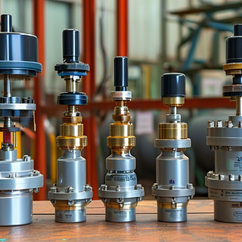
Electro-Hydraulic Valves: Definition, Functions, and Operating Principles
Electro-hydraulic valves combine electrical control with hydraulic power. An electrical signal moves a solenoid, proportional actuator, or servo mechanism. Hydraulic fluid then directs motion through a spool, poppet, or cartridge element. This arrangement controls pressure, flow, and actuator direction with greater precision than purely mechanical valves.
In practical systems, directional valves start or stop cylinder movement. Pressure valves protect pumps and limit actuator force. Flow-control valves adjust speed, often during lifting, clamping, or steering. Proportional valves provide gradual control, while servo valves support faster and more accurate positioning. A typical circuit may use a 24-volt signal, filtered oil, and a pressure sensor near the actuator.
Small details matter. During commissioning, technicians should check coil voltage, fluid cleanliness, return-line pressure, and spool response. A valve may appear faulty when contaminated oil is the real cause. Heat can also change viscosity and make motion less stable. I have found that pressure readings alone can mislead; flow measurements often reveal the actual problem. The division between valve types is not always perfect. Some proportional units deliver servo-like performance, but their repeatability depends heavily on installation and tuning. Global buyers should compare response time, pressure rating, leakage limits, control signals, and service conditions before selecting a design. Mistakes happen. A clear test procedure reduces them.
The Main Electro-Hydraulic Valve Types Available in 2026
In 2026, global buyers can choose among proportional, servo, directional, pressure-control, flow-control, and cartridge valves. Each type solves a different control problem. Directional valves move actuators between fixed positions. Proportional valves adjust speed and force through an electrical signal. Servo valves offer finer response, but they demand cleaner oil and tighter maintenance.
Fortune Business Insights valued the global hydraulic valves market at about USD 10.1 billion in 2023. Its report projects continued growth through 2032, supported by construction equipment, factory automation, and mobile machinery.
These figures show demand, not automatic suitability. A valve can meet the pressure rating yet perform poorly with unstable temperature or contaminated fluid.
Electro-hydraulic proportional valves suit presses, injection machines, and lifting systems needing repeatable movement. Servo valves fit demanding test rigs and high-response motion control. Cartridge and manifold-integrated valves reduce pipe connections and can improve compactness. Pressure valves protect circuits from overload, while flow valves help control cylinder speed. The boundary is not always clean. Some systems combine several types in one manifold. Buyers should compare response time, hysteresis, leakage, filtration level, electrical compatibility, and service access. A cheaper valve may create higher lifecycle costs. That lesson is easy to overlook.
How Electro-Hydraulic Valves Differ in Control, Pressure, and Flow
2026 Top Electro Hydraulic Valve Types for Global Buyers
How Electro-Hydraulic Valves Differ in Control, Pressure, and Flow
Electro-hydraulic valves convert electrical commands into precise hydraulic movement. The main choices include directional, proportional, and servo valves. Each type handles control differently.
Directional valves switch oil between ports. Their action is quick, but movement can feel abrupt. Proportional valves adjust spool position through an electrical signal. They provide smoother speed and force control. Servo valves offer finer response and lower hysteresis. However, they usually demand cleaner oil and more careful tuning.
Pressure performance depends on valve rating, circuit design, and load changes. A valve rated for high pressure is not automatically suitable for every machine. Check pressure drop, leakage, temperature, and safety margins. A neat pressure reading can still mislead. I have seen stable gauges beside cylinders that moved unevenly.
Flow control creates another important difference. A larger valve may pass more oil, but excessive size can reduce controllability. An undersized valve may cause heat, noise, and slow actuator movement. Compare rated flow with actual demand, not only catalog maximums. Signal resolution also matters during low-speed operation. Small command changes should produce predictable spool movement.
Installation experience often reveals the weak point. Poor grounding can distort feedback signals. Contaminated oil can damage precision edges. These details are easy to overlook. Buyers should request test data, control-signal requirements, pressure-drop curves, and service guidance before selection. Load behavior may still require on-site adjustment.
| Valve Type | Primary Function | Typical Control Signal | Typical Pressure Range | Typical Flow Range | Control Precision / Response | Main Flow-Control Characteristic | Typical Applications | Key Buyer Consideration |
|---|---|---|---|---|---|---|---|---|
| Solenoid-Operated Directional Valve | Switches hydraulic flow between ports or positions. | 24 VDC or 110/230 VAC On/off command | Up to approximately 315 bar | Approximately 5–120 L/min | Typical switching time: 20–60 ms Limited intermediate-position control | Discrete flow paths; flow is mainly determined by spool size and pressure drop. | General machinery, clamping, lifts, machine tools, and basic automation | Confirm spool configuration, allowable pressure drop, switching frequency, and coil voltage. |
| Electro-Hydraulic Proportional Directional Valve | Continuously controls actuator direction and speed. | 0–10 V ±10 V 4–20 mA | Approximately 210–315 bar | Approximately 10–1,000 L/min, depending on nominal size | Typical response: 20–100 ms Moderate positioning accuracy | Variable spool opening regulates flow; actuator speed changes with command input. | Mobile equipment, injection machinery, presses, material handling, and automation | Check command electronics, spool overlap, hysteresis, contamination rating, and required flow capacity. |
| Servo-Proportional Directional Valve | Provides high-accuracy closed-loop control of position, velocity, or force. | ±10 V Digital fieldbus or motion-controller command | Approximately 210–350 bar | Approximately 50–1,000 L/min | Typical response: 3–20 ms Very low hysteresis when correctly tuned | Fine spool metering supports rapid, repeatable control of flow direction and magnitude. | Test systems, metal forming, plastics machinery, precision presses, and flight or motion simulators | Requires clean hydraulic fluid, suitable feedback control, stable electronics, and careful commissioning. |
| Electro-Proportional Pressure-Relief Valve | Limits or adjusts maximum system pressure electronically. | 0–10 V 4–20 mA PWM input on some configurations | Approximately 50–350 bar | Approximately 5–300 L/min, depending on valve size | Typical response: 20–100 ms Pressure accuracy commonly within a few percent of full scale | Changes the pressure setting continuously while diverting excess flow when the limit is reached. | Variable-load systems, presses, mobile hydraulics, and energy-saving power units | Match pressure range to the required setpoint; verify minimum flow, pilot requirements, and heat generation. |
| Electro-Proportional Pressure-Reducing Valve | Maintains a controlled downstream pressure below inlet pressure. | 0–10 V 4–20 mA | Inlet: approximately 210–315 bar Outlet setting: approximately 5–250 bar | Approximately 5–100 L/min | Typical response: 30–120 ms Accuracy depends on load, temperature, and feedback | Regulates pressure in a secondary circuit independently of the main supply pressure. | Clamping, braking, pilot circuits, tooling, and multi-pressure hydraulic systems | Consider minimum pressure differential, leakage, downstream flow demand, and pressure stability. |
| Electro-Proportional Flow-Control Valve | Adjusts hydraulic flow to control actuator speed. | 0–10 V 4–20 mA PWM input on some models | Approximately 210–350 bar | Approximately 0.5–500 L/min | Typical response: 20–100 ms Flow accuracy is affected by pressure compensation and load changes | Meter-in, meter-out, or pressure-compensated metering controls flow independently or partially independently of load. | Actuator speed control, conveyors, winches, agricultural machinery, and process equipment | Choose pressure-compensated designs when load pressure varies significantly. |
| Electro-Hydraulic Pressure-Compensated Flow Valve | Maintains commanded flow despite moderate load-pressure changes. | 0–10 V 4–20 mA | Approximately 210–350 bar | Approximately 1–300 L/min | Typical response: 30–120 ms Better speed consistency than a simple throttle valve | An internal compensator maintains a relatively stable pressure drop across the metering orifice. | Mobile hydraulic functions, lifting systems, feed mechanisms, and synchronized actuators | Check compensator operating range, minimum pressure drop, and maximum allowable leakage. |
| Electro-Hydraulic Poppet or Cartridge Valve | Controls high flow through a compact two-way or multi-function cartridge element. | Solenoid on/off or proportional pilot control | Approximately 250–420 bar | Approximately 50–2,000 L/min | Fast switching for on/off versions; proportional versions typically respond in 20–100 ms | Large flow capacity with low pressure loss; can provide tight shutoff when correctly selected. | Presses, injection machines, hydraulic power units, high-flow manifolds, and mobile machinery | Evaluate cavity standard, pilot ratio, installation orientation, leakage class, and service access. |
| Electro-Hydraulic Check Valve | Allows free flow in one direction and blocks or releases reverse flow electrically. | Solenoid on/off or pilot-control signal | Approximately 210–420 bar | Approximately 5–1,000 L/min | Fast load-holding action; response depends on pilot volume and spring selection | Provides load holding, controlled release, and protection against reverse actuator movement. | Hoists, cylinders, presses, platforms, and safety-related load-holding circuits | Verify cracking pressure, pilot ratio, leakage requirement, shock loads, and emergency-release behavior. |
| Electro-Hydraulic Servo Pressure or Flow Valve | Uses electronic feedback to regulate pressure or flow with high dynamic accuracy. | ±10 V Digital controller or fieldbus command | Approximately 100–350 bar | Approximately 5–500 L/min | Fast closed-loop response; high repeatability when paired with pressure or flow sensors | Continuously corrects the valve command using measured hydraulic feedback. | Precision test rigs, forming equipment, closed-loop force control, and high-performance automation | Budget for sensors, controller tuning, fluid cleanliness, filtration, and system-level commissioning. |
Essential Selection Criteria for Global Industrial Buyers
2026 Top Electro Hydraulic Valve Types for Global Buyers
Essential Selection Criteria for Global Industrial Buyers
Global buyers are comparing proportional, servo, directional, pressure-control, and cartridge electro-hydraulic valves. Each type serves a different control problem. Proportional valves suit variable speed and force. Servo valves deliver faster response, but demand cleaner oil and tighter maintenance. Directional valves remain practical for rugged, repetitive motion.
Selection should begin with operating data, not catalog labels. Confirm maximum pressure, continuous flow, response time, duty cycle, oil viscosity, ambient temperature, and actuator volume. A valve rated at 250 bar may perform poorly if contamination rises. ISO 4406 cleanliness targets should match the valve’s sensitivity. Electrical factors also matter, including voltage tolerance, signal type, enclosure rating, and diagnostic feedback.
Market context supports careful investment. Grand View Research valued the global hydraulic equipment market at about USD 49.7 billion in 2023 and forecast a 4.5% compound annual growth rate through 2030. The report indicates expanding demand across mobile equipment, manufacturing, and energy applications. That growth does not justify choosing the most advanced valve automatically. Servo technology can reduce motion error, yet its higher filtration and tuning requirements may increase lifecycle costs. A lower-cost proportional valve may be the better fit.
Buyers should request test curves, leakage limits, certification documents, spare-part availability, and service response times. A common weakness is trusting nominal flow alone. Real performance changes with pressure drop, oil temperature, wiring, and control software. Total cost calculations should include commissioning hours, filtration, downtime, and training.
Installation, Maintenance, Standards, and Emerging Valve Trends
Electro-hydraulic valve selection starts with the working scene, not the catalog. Directional valves suit compact motion circuits, while proportional valves offer smoother speed and pressure control. Servo valves fit demanding positioning tasks, but they require cleaner oil and tighter filtration. During installation, keep the valve close to the actuator, support heavy tubing, and protect connectors from vibration. A level mounting surface matters. Small alignment errors can create large leakage problems.
Maintenance should include oil cleanliness checks, filter inspection, coil temperature readings, and response-time testing. ISO 4413 provides essential safety guidance for hydraulic systems, while IEC 60534-4 supports control-valve inspection practices. In field service, I have seen technicians replace a valve before checking contaminated oil. That assumption often fails. A simple pressure trend can reveal blocked filters, internal wear, or unstable pilot control. Keep service records with operating pressure, fluid temperature, cycle count, and replaced seals.
Standards are becoming more important as buyers compare suppliers across regions. MarketsandMarkets’ 2024 Industrial Valves report estimates the market could grow from about USD 78.9 billion in 2024 to USD 97.5 billion by 2029. This growth supports demand for connected valves, embedded sensors, and predictive maintenance. Digital feedback can identify drift before a cylinder stops. Useful, but not perfect. Sensors still need calibration, and network data can mislead operators when installation conditions change. New systems should combine diagnostics with physical inspection and documented safety procedures.